
Line Splitters as found in my Next Post as Well, under a Similar Topic. The Intent of this post is to show the Internal Construction of the x1 and x10 Line Splitter.
First, here’s an Interesting Basic Page on Meters:
Multimeters and Current Measurements
On that page, there are 4 drawings that show how running the conductor multiple times through the clamp increases the current read by the number of passes.
1 wire reads the actual current
Same wire through twice reads twice the current
Same wire through three times reads three times the current.
Etc.

Years ago, a friend had his own HVAC business, and he had a Black Analog Amprobe. It measured current via the clamp, and voltage via auxiliary leads that plugged into the bottom of the meter. He also had a line splitter, it was fashionably black. But the Line splitter had a Test Lead Set, and a “Shorting Bar”. The leads would be connected, in series, to the circuit or device being tested, then to the plug end of the splitter. The current would flow through the splitter, across the shorting bar plugged into the receptacle end of the splitter, and return to the circuit via the other side of the splitter. This gave convenient access to a place to clamp the meter, and a place to get x10 the reading for lower current circuits.

Of course, if you leave the shorting bar on, and plug it into a receptacle, you just created essentially a “Bolted Short”. I’m certain a number of people unfamiliar with it’s use left the shorting bar on and plugged it into a receptacle. So I guess they stopped selling it.
But he used it at times to set the Anticipator on the older Mechanical Thermostats used for heating, I most often saw it used that way in homes. Anticipators are actually tiny heaters in the thermostat. When you set the thermostat to 70º for example, if the thermostat shut-off at 70º, the burners shut down, but the blower generally stays on. It continues to run until the Heat Exchanger cools to a specific point, which opens a limit switch, and shuts down the blower too. (Modern furnaces often just use a timer). This additional time that it runs would leave your house warmer than 70º, it would overshoot the Set-Point. So, using the tiny Anticipator Heater, they fool your thermostat into thinking it’s warmer than it is, and it turns the burner off shy of the set point, and the temperature glides right into the desired value.
I saw an insane example of an Anticipator gone awry. At a home my son was living in at the time, he said the furnace kept starting and stopping too quickly, I looked at the Thermostat, and there is a thermometer on it. When the furnace was on, the thermometer would rapidly climb, indicating significant heating in the thermostat, causing the thermostat to open. I removed the thermostat cover and the Anticipator was set to all the way to one end. It looks like a flattened coil of wire, narrow on one end, wider on the other, and has “Longer” written underneath the adjustment tab with an arrow pointing in the direction to do that. Moving it towards Longer makes the furnace run longer.
The Anticipator is designed to be set to the current used by the Gas Valve (circuity in general, but the Gas Valve is a big chunk of the overall current, albeit a small current) of the furnace, so you set the Anticipator for the amperage experienced by your Thermostat to operate the Heat Cycle.
Thermostat open, Furnace Off.
Thermostat Closed, and a specific current flows, but be sure it’s in a Heat Cycle with the Gas Valve Electrically On and the Burners On, else you’ll get the wrong current. The Following Link has more, and an image at the bottom showing the Meter my friend used and the multiple winds of wire to get a good reading on it.
So, the Line Splitter, when used with the Test Leads and Jumper Bar, was a convenient tool for doing these, and similar, measurements.
THE GOOD OLD HEAT ANTICIPATOR
Below: The splitter disassembled was made for England.
Researching this, I discovered an incredible thing. Unlike Europe Countries, England uses what is referred to as Ring Circuits, and Power is Distributed throughout the House in Ring Patterns (Circular, figuratively) and the Rings are each operated at 32 Amps. Personally, I’m aghast.
UK – Wiring for Electric Appliances in Domestic Premises
Because they use 230V, (the U.S. uses 120V) they need less current for appliances, light bulbs, etc.
I=P/E The Formula for Current (I) Equals Power (P) Divided by Voltage (E)
1500 Watt Heater in the U.S. Divided by 120V means that the appliance uses 12.5 Amps, but in England, the same appliance uses 6.5 Amps. So they can use smaller gauge wires for the identical length wire runs, or run wires on much longer runs. In theory at least.
Wire Size is not dependent on Voltage, rather it’s dependent on Current. 32 Amps is 32 Amps, in America or England. Here, we’d have to use an 8 Gauge wire, the more common 10 Gauge wire is only good to 30 Amps. In the Ring, they’d have to do the same, though the proper cross section wire, smaller than 8 but larger than 10 could be manufactured, and likely they do.
The Astounding thing is that each Plug has to have a fuse in it for the wiring used by the appliance, and circumstances. That’s apparently why Twinkle Bulb Christmas Tree Light Sets in England have massive plugs, and everything else.
As mentioned earlier, England, and much of the remainder of the world, but far from nearly all, uses 230V, Japan used 100 Volts, a few countries 110V. Others, including the U.S., use 120V.
But England’s (and Europe’s) 230V has a similarity to our 120, although it’s twice the voltage. Unlike our 240V which is actually 120 volts to ground from each of the 2 Hot Wires and 240 Volts across them, England has the 230V on one Hot, therefore 230V to Ground and they use a Neutral.
World map showing the spread of plug types
Plug, socket & voltage by country
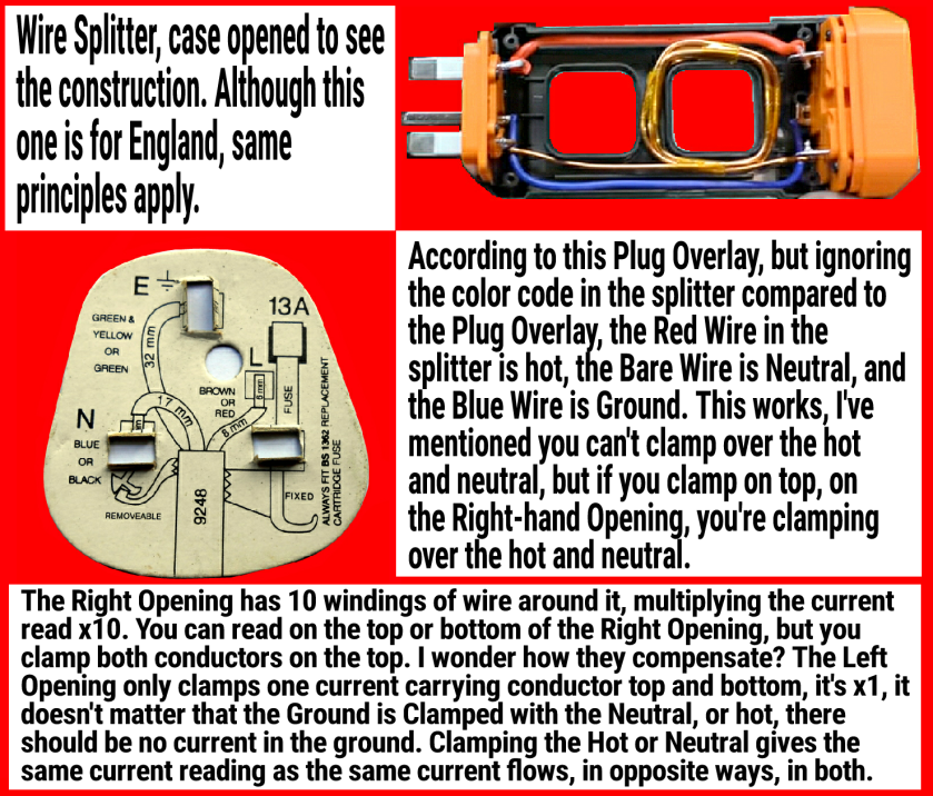
So, the Plug has the same set-up as ours, Hot, Neutral, and Ground. I found a Wiring Guide online that was apparently on the face of a British Replacement Plug, showing the wiring. In the Disassembled Line Splitter, the Ground is on the lower side as it is seen. According to the Plug Terminal Positions on the guide (not the color code from it), the Bare Wire in the Splitter is Neutral, and the Red Wire Hot. The Blue Wire is Ground.
You can measure current on the Hot or Neutral Side of a circuit with a Clamp Ammeter, but not the Hot and Neutral at the same time, since Equal but Opposite current flows nullify each other.
But on this line splitter, the Hot Wire goes past the multiple wraps of the Neutral Wire for the x10 position, so that means you’re clamping both. Though 10 wraps of the Neutral Wire will yield a value 10x a Single Wire Reading, and I’m sure that largely overpowers the single conductor, it must still effect it, or they have compensated in a different way.
