
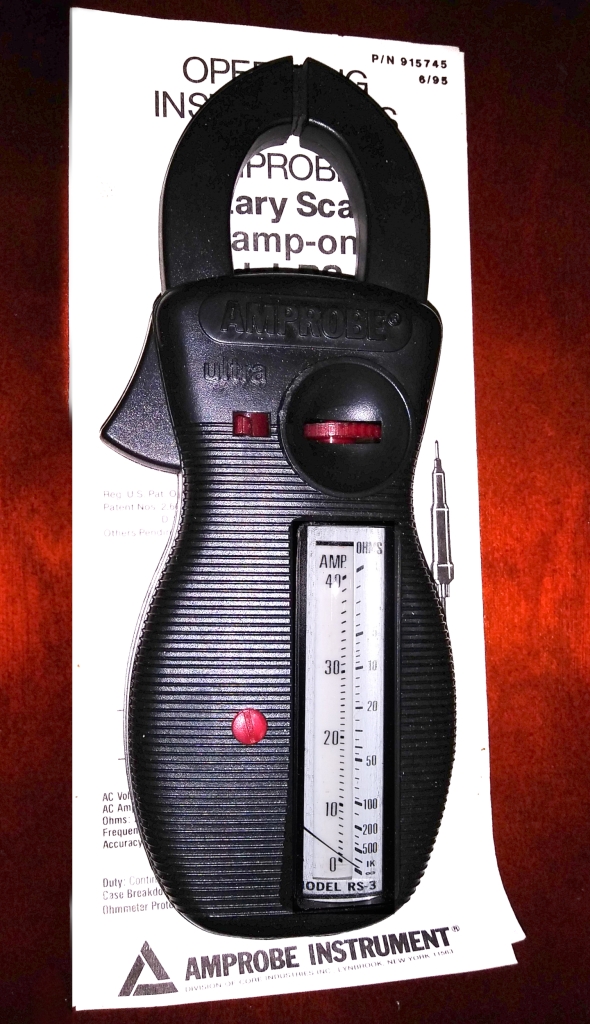
A Historic Treasure that works, an Unused Amprobe R3 Pro Clamp Ammeter. It’s older, Analog, Reads A.C. Voltage and Current (Not D.C.), and has a Continuity/Resistance Reading for about 500 Ohms and Less (in practicality).
A friend with a Refrigeration Business had one, it’s the 1st Amprobe R3 and for that matter, the 1st Clamp Ammeter I ever saw. His was made from a Harder Plastic, my model being more recent. There is a Red and Black Voltage Testing Lead (used with Jacks on the Bottom of the Meter), and a Yellow Test Lead used to Measure Resistance/Continuity used in Conjunction with either the Red or Black Voltage Tester Lead (only one of those leads plugged into the Left Meter Jack on the Bottom as Viewed from the Front), and the Ohmmeter Lead plugged into a specific terminal on the Right Side of the Meter as viewed from the Front.
Below, Click on Images for a Close-Up


The Kit includes:
- Organizing Carrying Case
- Amprobe Clamp Ammeter
- Voltage Test Leads (2)
- Insulated Alligator Clip to be used with a Voltage Test Lead (1)
- Resistance/Continuity Test Lead (1)
- Line Splitter (with X1 and X10 Positions)
- Shunting/Shorting Bar to be used with the Splitter (in VERY SPECIFIC AND LIMITED APPLICATIONS)
- RAL-4 Cord with a Receptacle on one end, and Insulated Alligator Clips on the other end, to be used in Specific Circumstances with the Splitter and Shunting/Shorting Bar.
- Instructions, Registration Information, and other Promotional Information
The Resistance/Continuity Test Lead is missing the Metal Testing End for contact with the circuity, I’ll try and Repair/Replace it as possible. This was the only Deficit Noted.
The Rotatory Scales Are:
- Amp 6, 15, 40, 100, 300
- Volt 150, 300, 600
Ohms is on a Non-Rotary Scale of 0 to Infinite Ohms, on a Logarithmic Scale that is only semi-accurate in the 0 to 100 Ohms. As this is not a Digital Meter, it’s designed to show Approximate Resistance for Coil Resistance Purposes and for Continuity.
The Instructions are Shown on this Blog, they appear to be from June 1995 in terms of the Revision of the Instructions, the Meter Dates from 1995 or Newer.
PDF of the Meter in general, in an Easier to Read format:
OPERATING INSTRUCTIONS:
AMPROBE® Rotary Scale Clamp-on Model RS-3
Original Instructions Included with this Meter (click on for Close-Up):
Cover and Pages 1 and 2


Pages 3, 4, and 5


OHSA Requires the Use of Insulated Gloves, usually with Leather Outer Protective Gloves (Prevents Damage to the Rubber Insulated Gloves) when working on Equipment with Exposed Energized Parts at 50 Volts or More. Although I doubt the average Home Tinkerer is equipped with Insulated Gloves, it does highlight the need to keep one’s hands well away from Live Conductive Parts when testing. A Shock Applied in a specific manner can be fatal even if the voltages do not seem to be particularly prone to cause death. After working 25+ years in Heavy Industry (around 15,000 Volts and Less), the worst shock I’ve received was at home. For a Double “Light Switch” Work Box, I turned off the circuit to one half, leaving the other half lit for the light above where I was working. While Replacing the Light Switch it didn’t want to insert back into the box, so I manipulated the Wiring in the Box and Touched the Energized Terminals on the other Switch. It went in one arm, across my chest, to the other arm, and back to ground. I let out a scream and frightened my wife who was standing there. It’s fortunate it wasn’t fatal, this is the worst scenario for being shocked, right across the chest. BE CAREFUL.
Having a Meter, knowing when and how to use it (Safely), is indispensable.
For the Various Ranges for the Clamp Ammeter and Voltage Functions, the Meter Display Rotates to change the Meter’s Input Circuit for the Anticipated Use and Range and to offer a Scale Suitable for the Selected Input.
This Clamp Ammeter uses the Alternating Magnetic Field of an A.C. Conductor to Induce an Altering Magnetic Field in the Laminated Sections of the Clamp and it is has Coils of Wire Around the Laminated Sections of the Clamp that change the Alternating Magnetic Field into an Electrical Current for the Meter Movement. The Amprobe R3 is a Current Transforming Type.

Not uncommon these days, though, is a Meter Design that uses a Hall Effect Sensor, and due to this Technology, D.C. Currents can be Measured as well as A.C., see the following article. If your Clamp Ammeter has Metal Exposed on the End of Both Clamp Halves (in the Center), it’s likely a Current Transforming Clamp Ammeter, and if one Side is Metal and the other is covered in the Molded Plastic of the Clamp Shell, then it’s likely a Hall Effect Clamp Ammeter.
What are Hall Effect (A.C. / D.C.) clamp meters?
This Clamp Ammeter can only Measure the current if one if the Wires is Separated from the other. If you look at a standard Table Light Cord, both wires are bound together for convenience. If you clamp both wires, the Meter will not read the current used by the lamp, since the Current in one wire is equal in amplitude but in the opposite direction of the current in the other wire, and they cancel out. Though one could separate the wires and measure just one, either one, to read the current, it is needlessly destructive. Amprobe included a Splitter with this Set-up that is plugged into the wall (REMOVE THE SHORTING BAR FIRST), and the Lamp Plugged into the Splitter. To Avoid Issues with the Shorting Bar, one can Plug the Lamp into the Splitter, then the Splitter into the Receptacle, as it would be impossible for the Shorting Bar to be on the Splitter when it’s plugged in.

The SHORTING BAR has a VERY SPECIFIC USE, DO NOT LEAVE IT ON THE SPLITTER WHEN THAT SPECIFIC USE PROCEDURE IS NOT BEING PERFORMED.
Click on the Images Below for a Close-Up


Click on the Images Below for a Close-Up


Click on the Images Below for a Close-Up, this is the Purpose of the Shorting Bar. The Splitter Plugs into the Cord (RAL-4) shown to the Left, and the Insulated Alligator Clips are used to Put the Splitter/”RAL-4 Cord” In-Series with a Motor Lead or Component, the Shorting Bar Completes the Circuit so that the Splitter can be used to Read the Current.


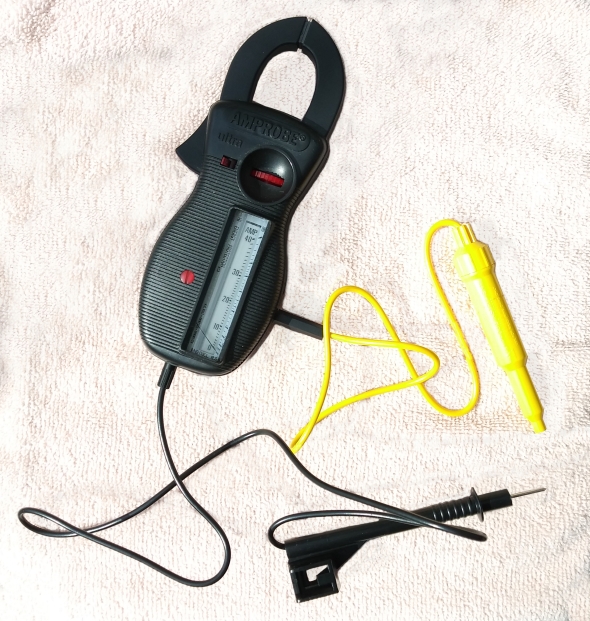
The Meter, Accessories, and Challenge in getting good photos of a Black Meter in Detail.
On the Left of the Meter, the Shorting Bar (Orange) and Line Splitter (Black). The Meter itself, with the 40 Amp Scale Showing. The Yellow Probe to the Right of the Meter is for Resistance and Continuity. It takes a AA Battery, and the Probe is Broken Off, the only item in this set that was damaged.
The RAL-4 Leads has the Black Receptacle and Red and Black Leads, with Red Insulated Alligator Clamps at the end. The Black Insulated End, seen with the RAL-4 Leads, is actually for the end of one of the Voltage Testing Leads, (Bottom Right), and can be installed and removed as needed.

Meter, Line Splitter, and Shorting Bar. The Shorting Bar Literally Shorts Across the Plug-End of the Splitter, and is only for use with the RAL-4 Leads as shown above. The 40 Amp Rotary Scale can be seen on the Meter, and the Stationary Scale for Resistance is also clearly shown.
When the Splitter is Plugged-in to a Receptacle, there is a Voltage Test Point on either Side of the Splitter, so that the Voltage Across the Line, whether or not an Appliance or Light is plugged into the Splitter, can be Measured with the Voltage Test Leads and the Rotary Dial Set to the Appropriate Voltage Range. The Voltage Test-Points do not work when the RAL-4 Cord is used.
NEVER PLUG THE SHORTING BAR IN WHEN THE SPLITTER IS PLUGGED-IN TO A RECEPTACLE, INJURY MAY RESULT, AND IT WILL ARC AND MAY DAMAGE THE SPLITTER, THE SHORTING BAR, AND IT WILL LIKELY TRIP A BREAKER IN THE CIRCUIT.

Below is the Meter (the Display should be on the Voltage Scale, I forgot to Set it for the Photos. The Voltage Scales are Red. The Meter is being used to hold the Voltage Probe, the Voltage Probe is designed to work work with the Clamp. This is a great design, as the Reach of the Probe on the Meter allows the Hand to stay further away from Energized Parts. The Image below that is the Same Photo, as originally taken, before I reworked it. The Black Meter just wasn’t showing up on Flash Photography, from my Cellphone, but I tried in the sun and underestimated the significance of the shadows.


This is the same situation. The Image shows the Connection of the Resistance/Continuity Attachment to the Meter, requiring the use of one of the Voltage Test Leads in the Position Shown. The Yellow Leads plugs into the Right Side of the Meter when viewed from the Front. The Image Below that is the Same Image, that I reworked, and but I also removed the Shadows from the Lower Image, but decided to redo the Background Entirely.

Miscellaneous Information Included with the Meter. Click-on the Image for a Close-Up.


There are still people here who work with these things, although they are also about to become a thing of the past, the vast majority already carry digital devices.
I only know from what I see, as you know, I have no idea about this kind of things, technology, electricity, computer science, since school I was totally of letters, humanities subjects, those who are withdrawing from teaching, history, philosophy, literature …
Hey, how come you don’t share the posts on social networks? I, as soon as I decide to make my paid blog (Pro), I will return to do what I did before, upload the posts to all social networks, the views can be up to five times.
LikeLiked by 1 person
How would I make them available to Social Networks?
The Meter, for AC, is fine, Digital Doesn’t always imply better, some Digital are poorly designed.
You need to know the equipment and it’s limitations. We had one brand of Voltmeter at work, Digital, and occasionally it would say that the wires weren’t energized when they were. I had someone bring it to my attention from their meter, and then I saw it on mine. With Electronics, if something gets locked-up in the electronics, the display doesn’t read, the safe Policy is to Test a Known Energized Source, then Test the Desired Point, then test the known Energized point again, to be sure the meter is working. With Analog Meters, like this one, there is no Battery, The Meter has no Electronics in the sense that modern meters do, since it’s much simpler, it’s less likely to fail to measure. But Electronic Meters are often safer, and some are very tolerant of being incorrectly connected, where such a thing might destroy the movement in an Analog Meter.
LikeLiked by 1 person
In social networks? Putting the link of the post, the same as when you upload other articles, like everything I publish, the same, in the case of this post you would have to copy the link (https://drartaudnonpolitical.wordpress.com/2022/04/04/an-unused-amprobe-r3-current-clamp-ammeter-a-piece-of-history/) and paste, nothing else. Well, I also put the title, but because at the beginning, it did not come out and only the link was left, but then they fixed it.
In the other networks, of course, it is not necessary.
I thought you knew it, if you do it from the beginning, everyone does it, everything you see in Gab or in any social network, is done this way, otherwise, you could only publish from uploading from the hard disk.
LikeLiked by 1 person
Great blog Dr. some good reference material !
I bet that shock experience you had was scary
For sure . Thanks for posting this will come in
Handy !!
LikeLiked by 1 person
I worked on motors than ran on up to 15,000 volts, we had periodic catastrophic failures of electrical equipment, explosions, fires, and the worst I was shocked was at home. Always be vigilant. The meters are interesting, because my friend had one, it means more to me. He had an Analog Millivolt Meter, I skunked that one day, I connected it to 24 Volts AC, I thought a Warp Switch was a Thermopile (800 Milivolts DC). Digital Meters are much more tolerant of improper connections (in general), but I’ve seen a Digital Meter fail to measure a voltage that was there. The best policy is to test the meter on a known energized circuit, then test the desired point, then test the known energized circuit again.
Thanks for the positive feedback.
LikeLike